")
Most of the Menu Buttons will expand/hide the submenu controls.
Expandable buttons:
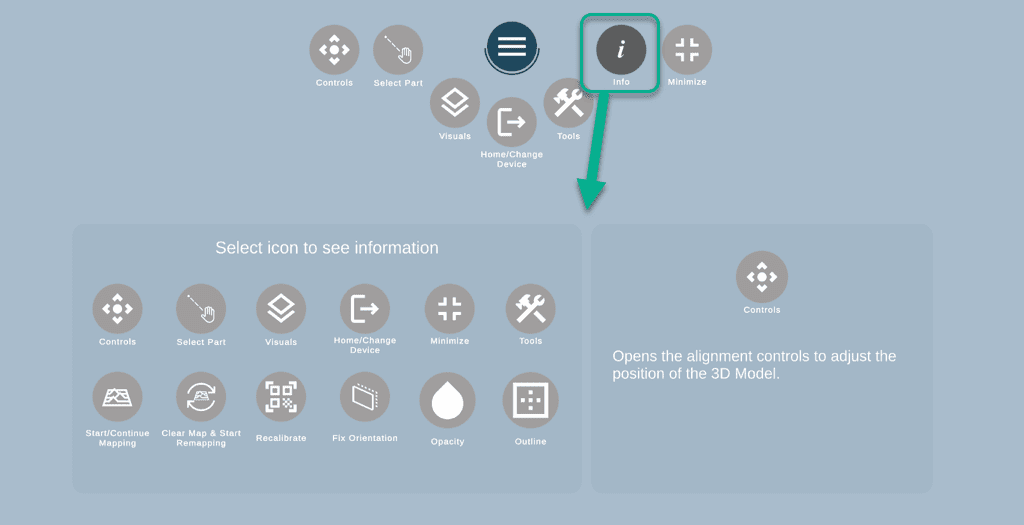
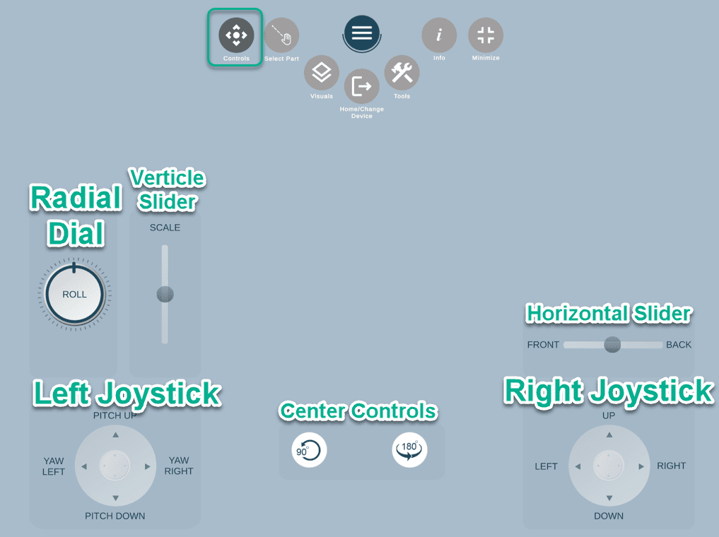
![]() Controls – opens the alignment controls to adjust the position of the 3D Object.
Controls – opens the alignment controls to adjust the position of the 3D Object.
![]() Select Part – allows the user to select a different part for the alignment to the QR target.
Select Part – allows the user to select a different part for the alignment to the QR target.
![]() Visuals – opens the Visuals’ panel, where the user can select the view/hide parts and adjust the opacity and outline.
Visuals – opens the Visuals’ panel, where the user can select the view/hide parts and adjust the opacity and outline.
![]() or
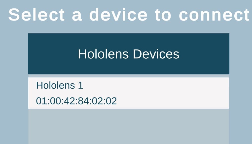
or ![]() Home/Change device – exits the Augmented Reality feature and allows changing the device.
Home/Change device – exits the Augmented Reality feature and allows changing the device.
![]() Tools – expands a menu with orientation, mapping and other tools.
Tools – expands a menu with orientation, mapping and other tools.
![]() Info Toggle – displays the button names for easy reference.
Info Toggle – displays the button names for easy reference.
Non-expandable buttons:
![]() Minimize – takes to the drawings and 3D viewer/main feature area.
Minimize – takes to the drawings and 3D viewer/main feature area.
![]() Closes all opened settings to clear the assembly view.
Closes all opened settings to clear the assembly view.
You can learn more about expandable buttons in the sections below.
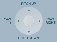
Pitch up – tilts the model up using the target as a pivot point.
Pitch down – tilts the model down using the target as a pivot point.
Yaw left – angles the model to the left (when standing at the far end) using the target as a pivot point.
Yaw right – angles the model to the left (when standing at the far end) using the target as a pivot point.
 Roll CCW – rotates the model incrementally counter clock-wise.
Roll CCW – rotates the model incrementally clock-wise.
 Scale Up – Increases the scale of the model expanding out towards the far end.
Scale Down -Decreases the scale of the model.
Up – moves the model’s elevation up.
Down – moves the model’s elevation down.
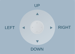
Left – moves the model to the left.
Right – moves the model to the right.
Horizontal Slider
![]()
Center Controls
![]() Rotate 90 – Rotates the model 90 degrees to the left around the X-axis.
Rotate 90 – Rotates the model 90 degrees to the left around the X-axis.
![]() Rotate 180 – Rotates the model 180 degrees to the left around the Z-axis (end -to end).
Rotate 180 – Rotates the model 180 degrees to the left around the Z-axis (end -to end).
![]() Select Part of the menu allows the user to select a different part for the alignment to the QR target.
Select Part of the menu allows the user to select a different part for the alignment to the QR target.
Click here to learn more about this Select Part.
")
Parts List (on gray background on the right) – by default all parts are displayed. Select individual parts to be hidden, or select “Small Parts” to hide all small parts (Nuts, Bolts, Welds, etc.)
![]() Opacity – Adjust the opacity of the 3D Object (100, 75, 50, 0)
Opacity – Adjust the opacity of the 3D Object (100, 75, 50, 0)
![]() Outline – Adds an outline to the 3D 0bject (as shown in picture).
Outline – Adds an outline to the 3D 0bject (as shown in picture).
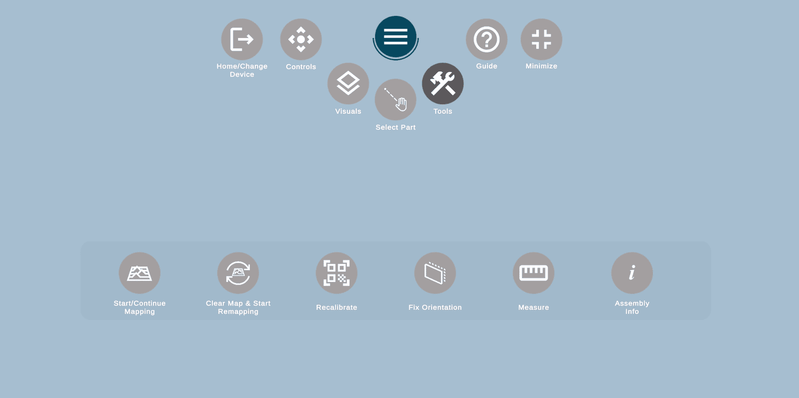
 Start/Continue Mapping. You will need this button if you didn’t map the area initially, or didn’t map the full area you need, and want to expand your current working area.
![]() Clear Map & Start Remapping. This option is useful when you want to clear your map (to work on the opposite side of the assembly, align an assembly by section etc.) as it will completely erase your current map and will allow you to map a zone again.
Clear Map & Start Remapping. This option is useful when you want to clear your map (to work on the opposite side of the assembly, align an assembly by section etc.) as it will completely erase your current map and will allow you to map a zone again.
![]() Recalibrate. It will remove the current 3D model and show the pop-up to rescan the QR code anew.
Recalibrate. It will remove the current 3D model and show the pop-up to rescan the QR code anew.
![]() Fix Orientation. If the model is completely out of place, and you are not sure how to fix it, this option will do a hard reset and set up the 3D model and bring it back to the QR code.
Fix Orientation. If the model is completely out of place, and you are not sure how to fix it, this option will do a hard reset and set up the 3D model and bring it back to the QR code.
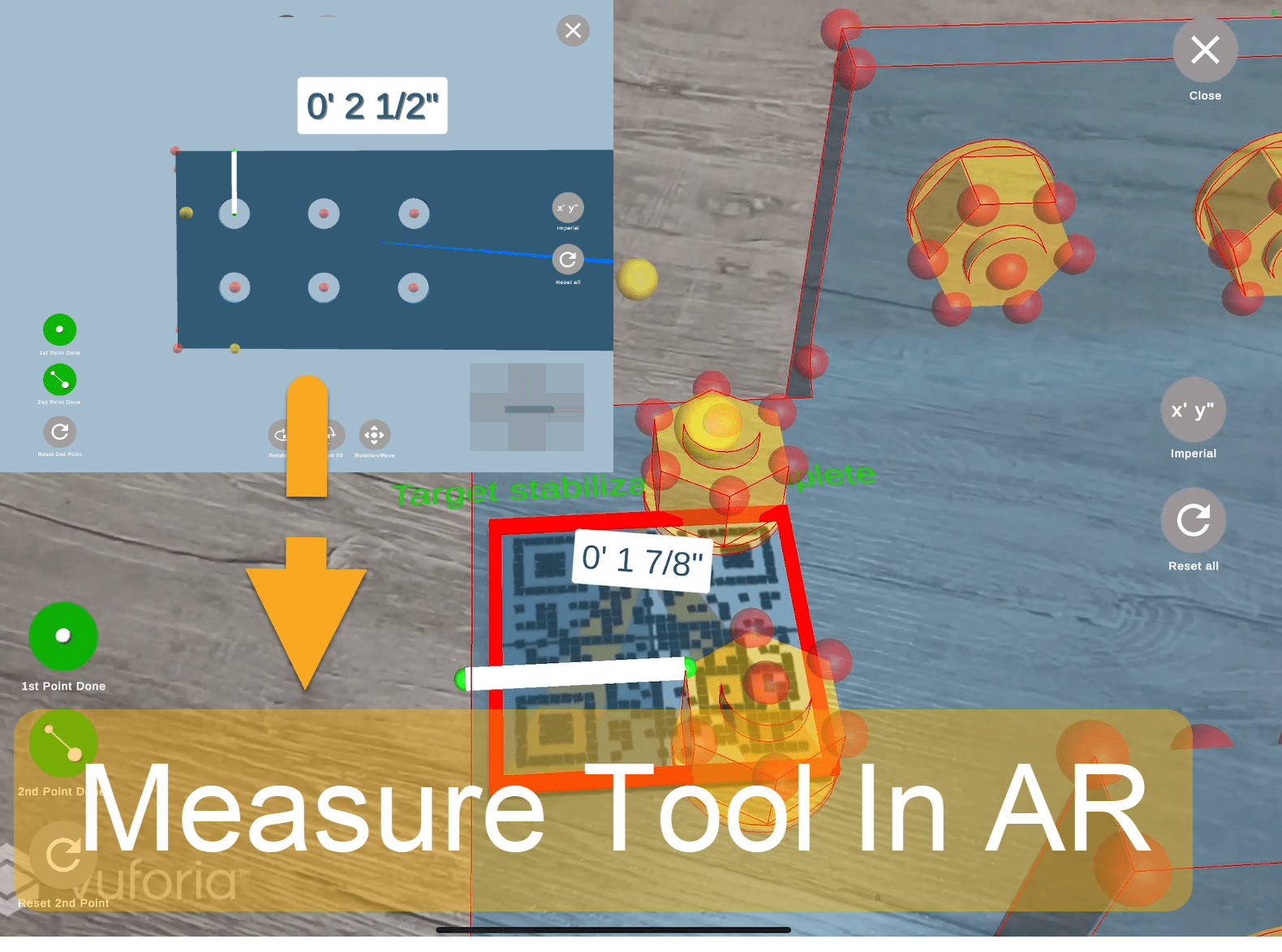
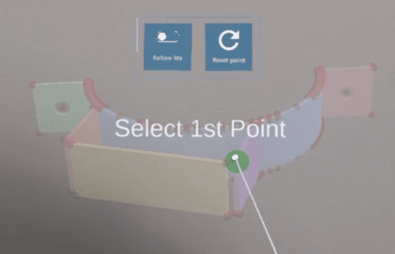
![]() Measure. This tool will allow you to measure the distance between 2 points on the same assembly.
Measure. This tool will allow you to measure the distance between 2 points on the same assembly.
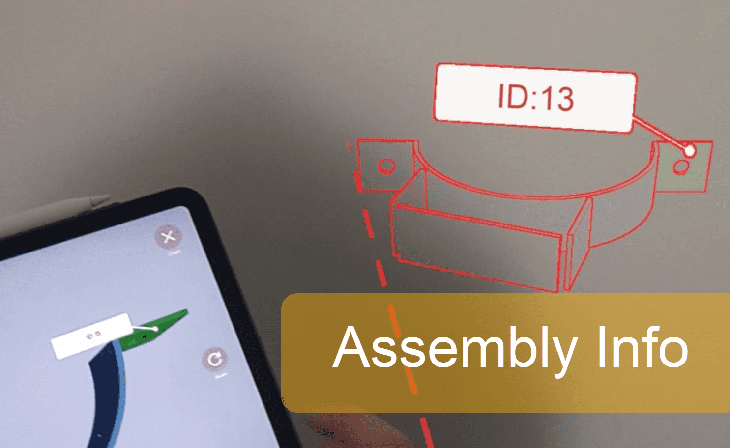
![]() Assembly info will be helpful to know the part name. For the Inventor/Revit and Solid Works files, it will also show weight and some other details if they are present on the model.
Assembly info will be helpful to know the part name. For the Inventor/Revit and Solid Works files, it will also show weight and some other details if they are present on the model.