Camber Tool
Please watch the video to learn about the main Camber workflow or follow the guidelines below.
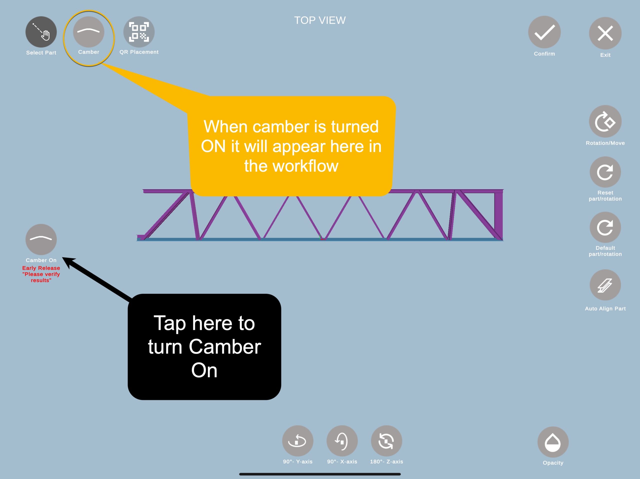
Note: 1)Once you cambered the assembly, you can now go to Auto-Fab/Fab-Assist and see the model in AR.
2) The feature is out of experimental stage – please skip that step.
Camber Tool
Using the camber tool in FabStation is useful when working on larger assemblies, like bridges, where camber is often required. Applying camber allows you to view the assembly hologram in Auto-Fab/Fab-Assist with the camber curvature of these structures, allowing for more precise alignment and inspection.
How to Apply Camber to Assemblies
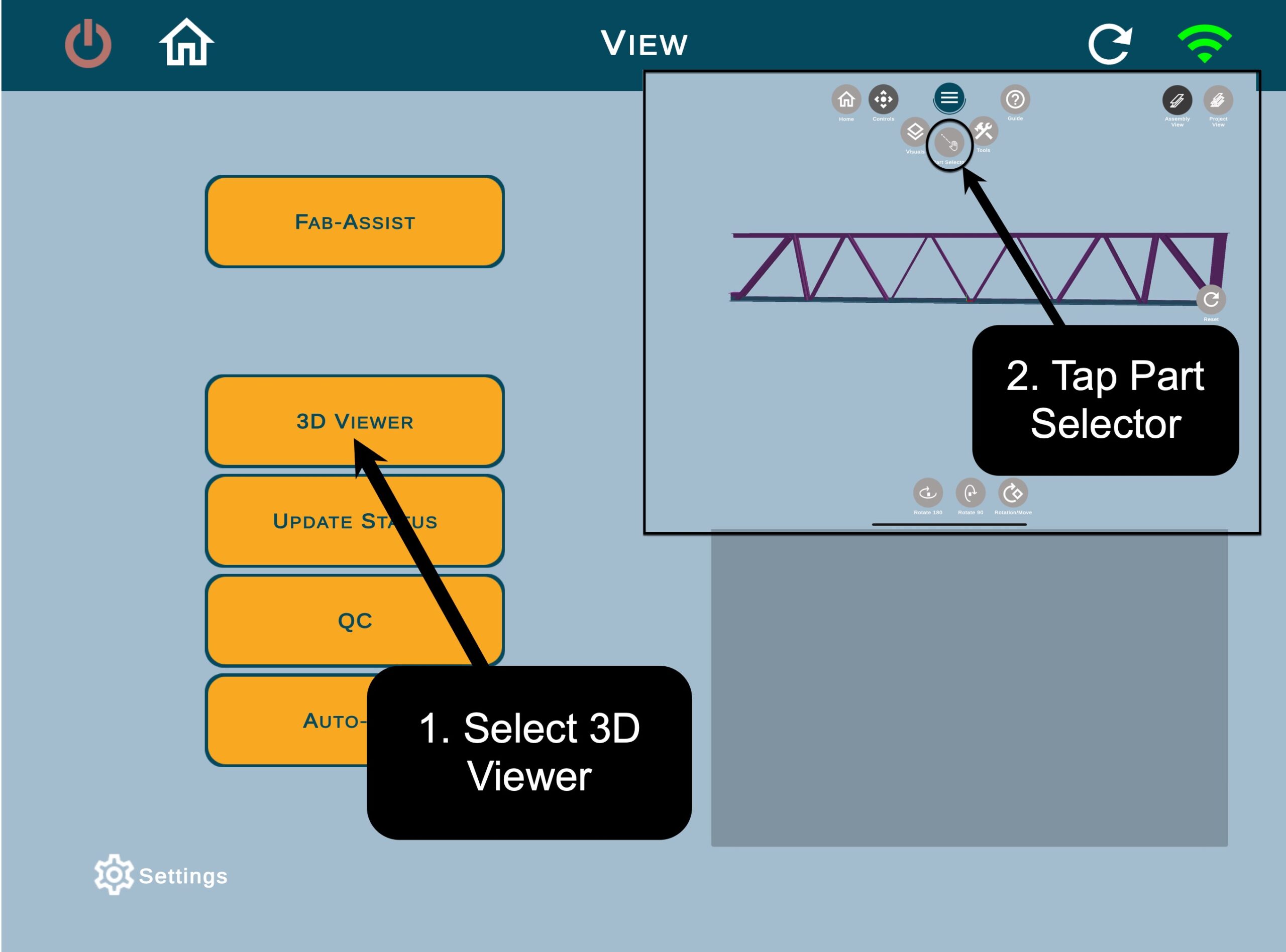
Step 1: Part Selector and Hologram Orientation :
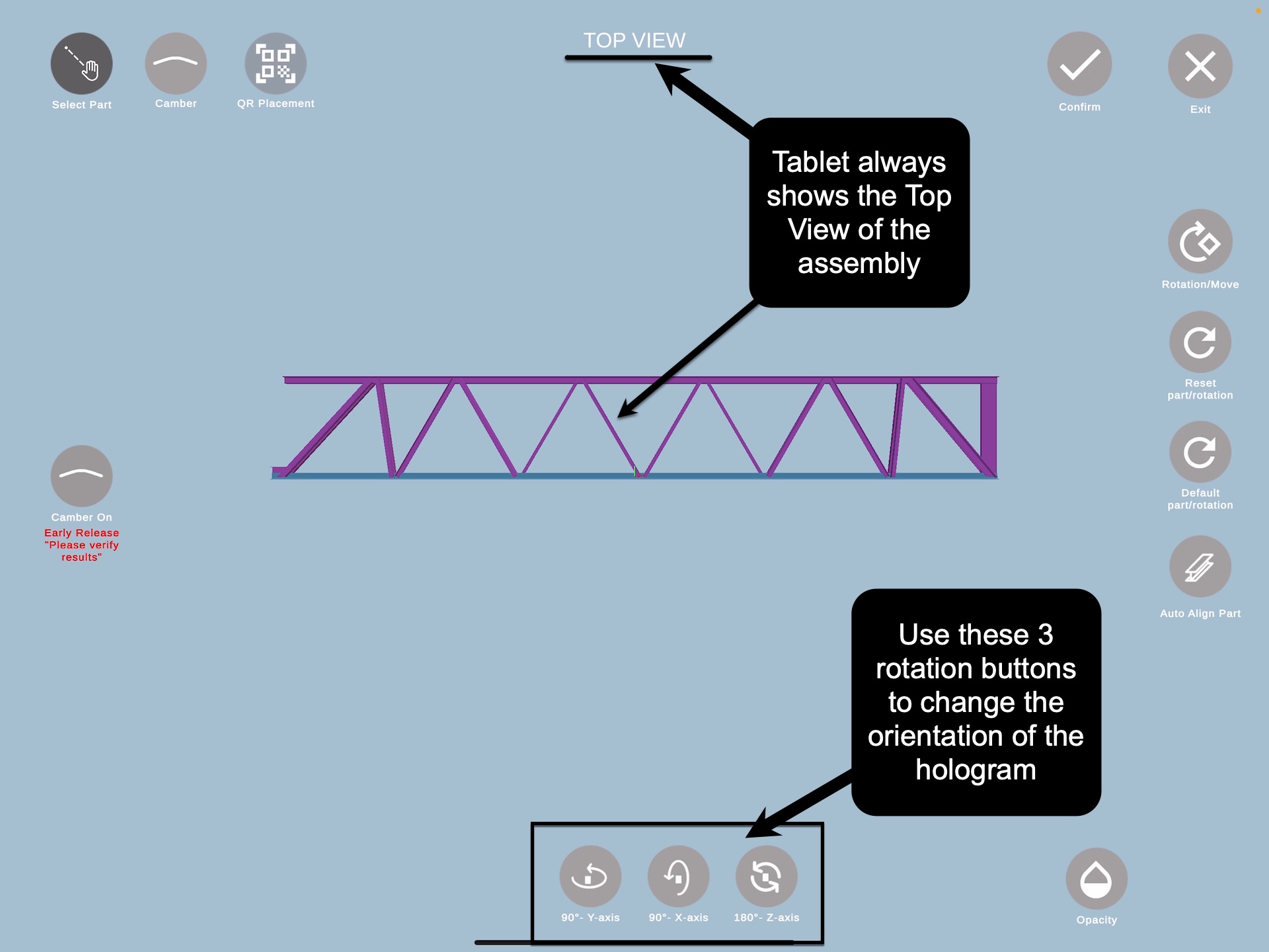
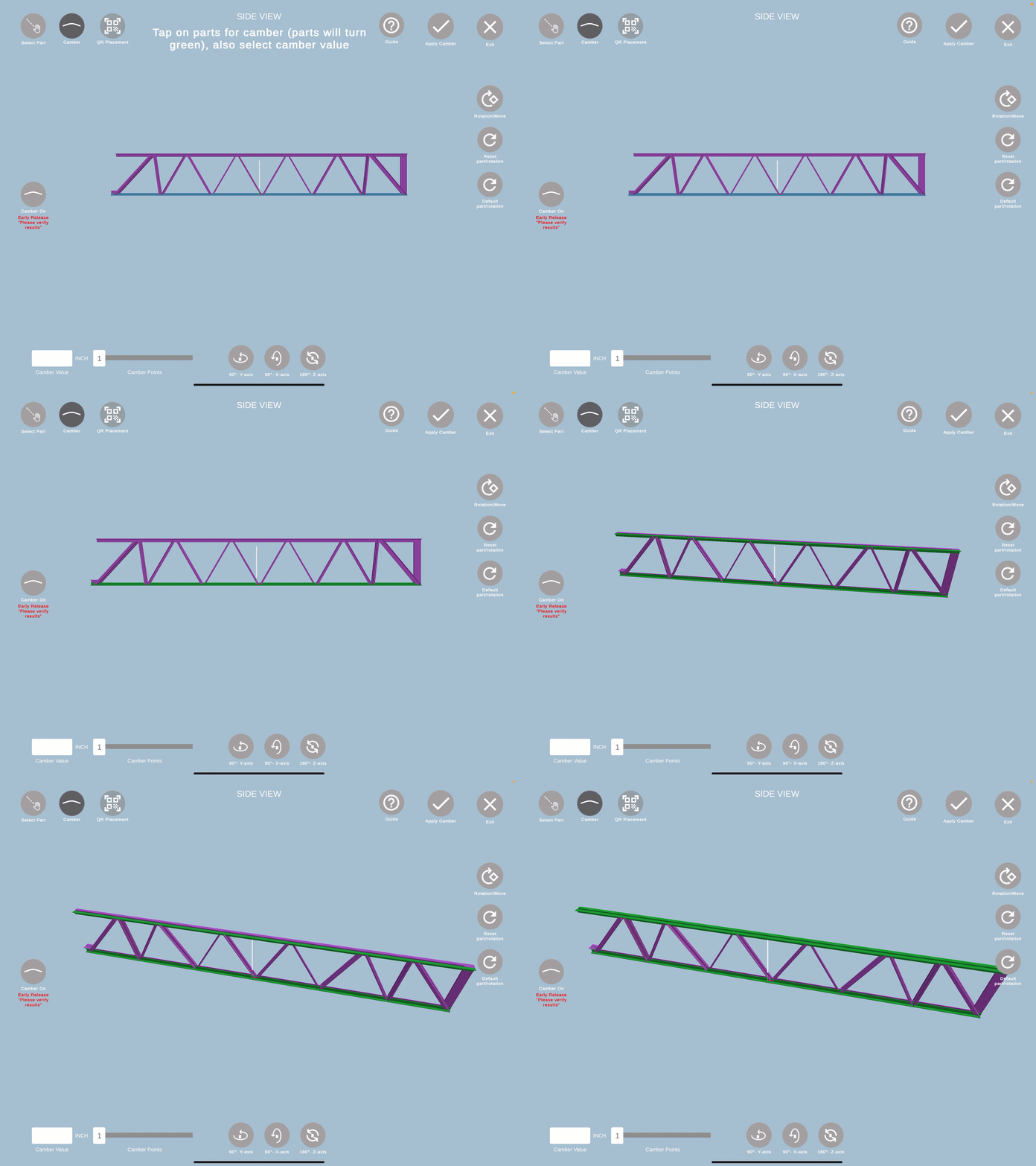
- Adjust main part and the hologram orientation. This tablet view shows the top view of the assembly, as if you were looking at the assembly from a bird’s-eye perspective.
- Note the tablet will also place you the left side of the tablet view; rotate the assembly accordingly.
- Click here to learn more about the Part Selector orientations.
- Once oriented, tap Confirm at the top right.
The Part Selector view always shows you the Top View of the assembly, the Camber view always shows your the Side View of the assembly
Step 2: Apply Camber
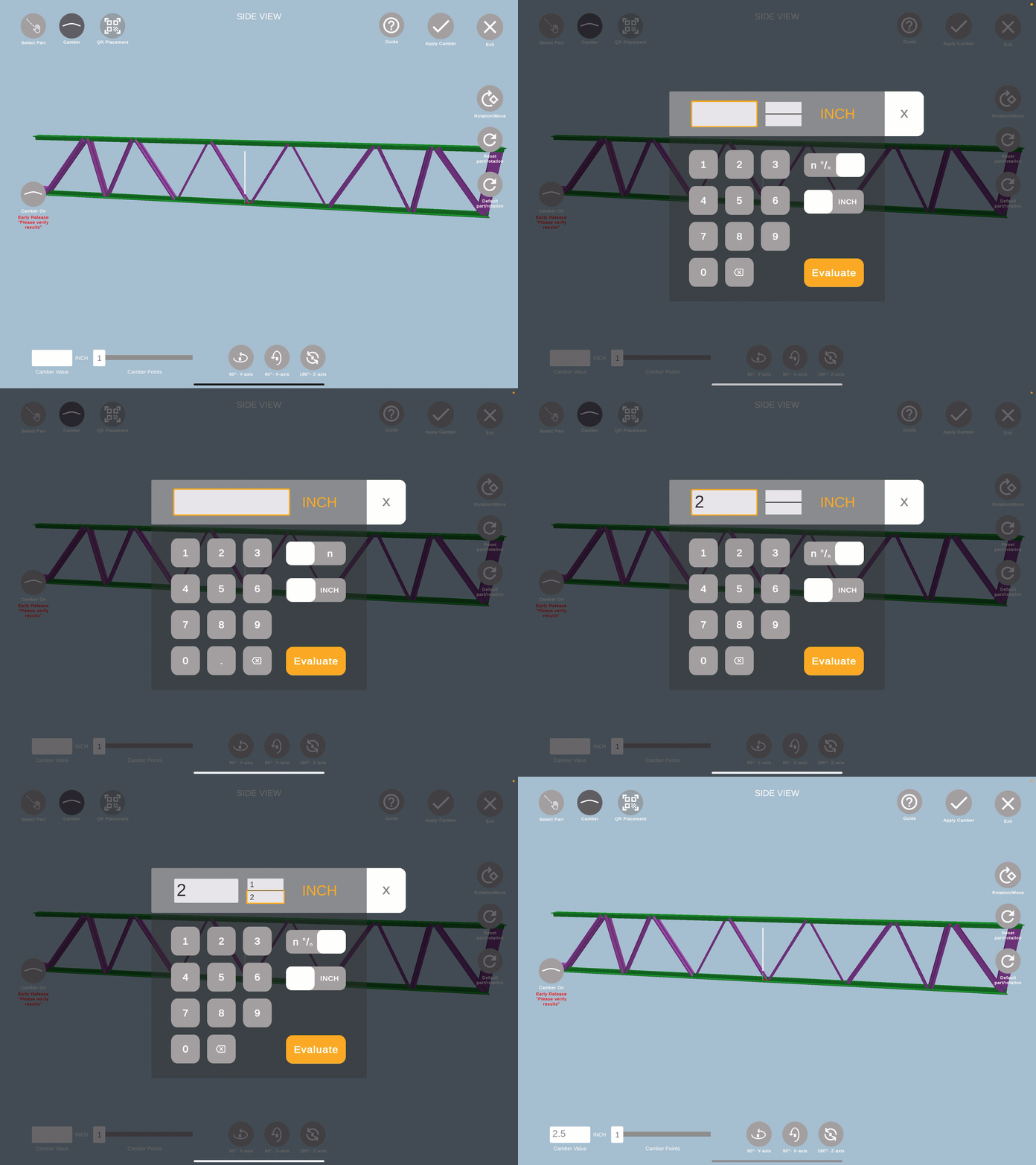
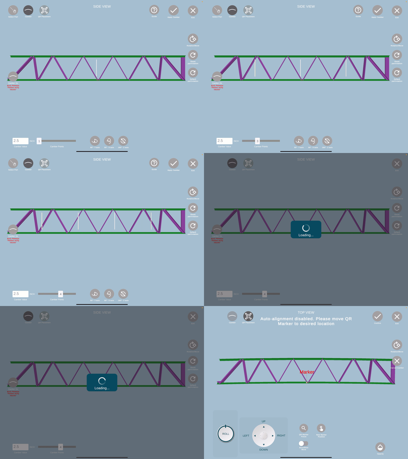
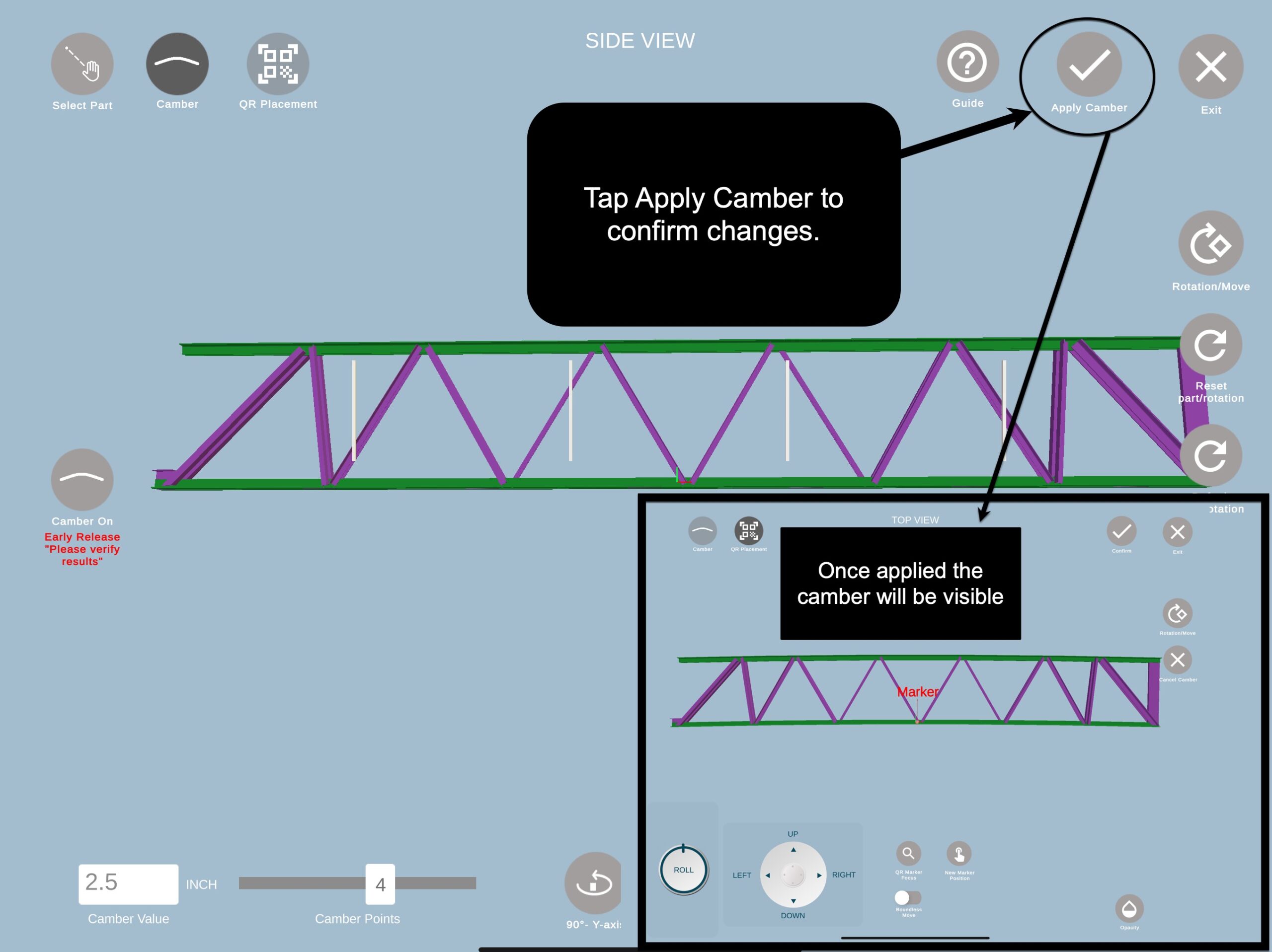
Note: The tablet now shows a side view of the assembly.
1. Select the parts to camber by tapping them; selected parts turn green. If applying camber to both top and bottom parts of the assembly, make sure all are highlighted green.
Step 3: Adjust QR Code Placement: Next you will be prompted to adjust the QR placement.
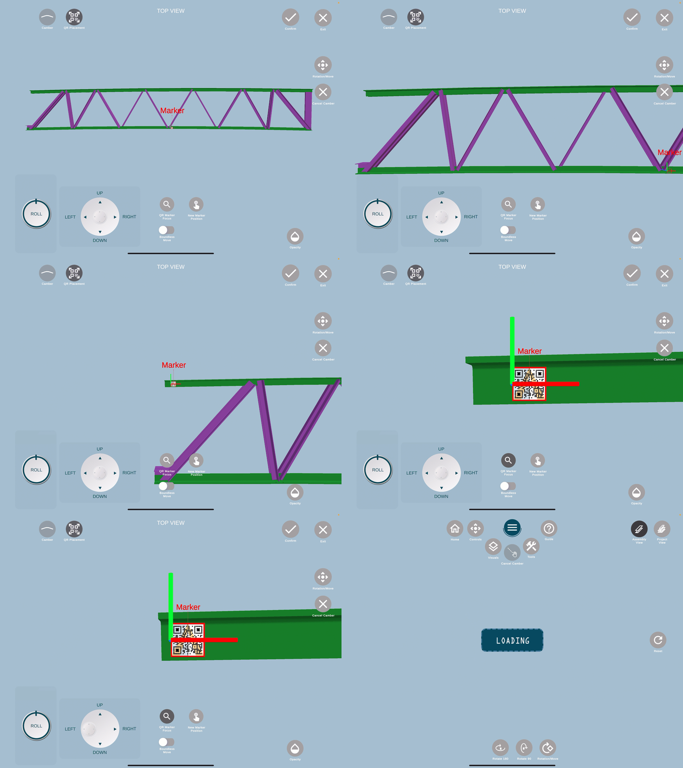
With camber applied, the QR code will load at the center of the assembly. Manually reposition it to the left side of the tablet by using the New Marker Position option and tapping on the left side of the assembly. Keep the QR code close to the edge of the assembly, placed facing horizontally on the assembly. Use the controls to micro-adjust the QR code.
Click Confirm once the QR code is adjusted.
Click here to learn more about the QR placement.
Other tools such as Measuring Tools are currently not available when Camber is turned. Cancel Camber to use these features.
With camber applied, tap Home. Then select Auto-Fab/Fab-Assist to view the assembly hologram with the applied camber. Follow the standard guidelines to align the hologram assembly.
